Physical Cell ID Planning
PCI planning is one of the most important things to understand while planning an LTE Network and it is usually left untouched in most of the LTE manuals and text-books. As already explained, the PCI is decoded using the SSS and the PSS and can be given by the following equation
PCI = 3*SSS + PSS
Where, PSS = 0,1,2
SSS = 0,1,2, . . . . 167
PCI = 0,1,2, . . . . 503
So, if SSS is equal to 5 and PSS is equal to 1 then the PCI would be 16. A basic rule of thumb is that the neighboring cells should not have the same “PSS” value. Usually, a site with 3 cells use same SSS value but different PSS value such that the PCIs for cell 1,2 and 3 will be 0,1 and 2.
Within the cell, the channels are scrambled using the PCI which means that the PCI serves as the seed for the cell’s permutation algorithm. That’s why, the UE has to decode the PSS and SSS before reading any other channel as it needs to get the PCI which tells about the permutation used in the cell.
Rule#1 Usage of same PCI
Since we have 504 PCIs so this rule is usually not difficult to follow.
- The same site should not use the same PCI again on the same frequency
- The NBRs of the site should not have the same PCI on the same frequency
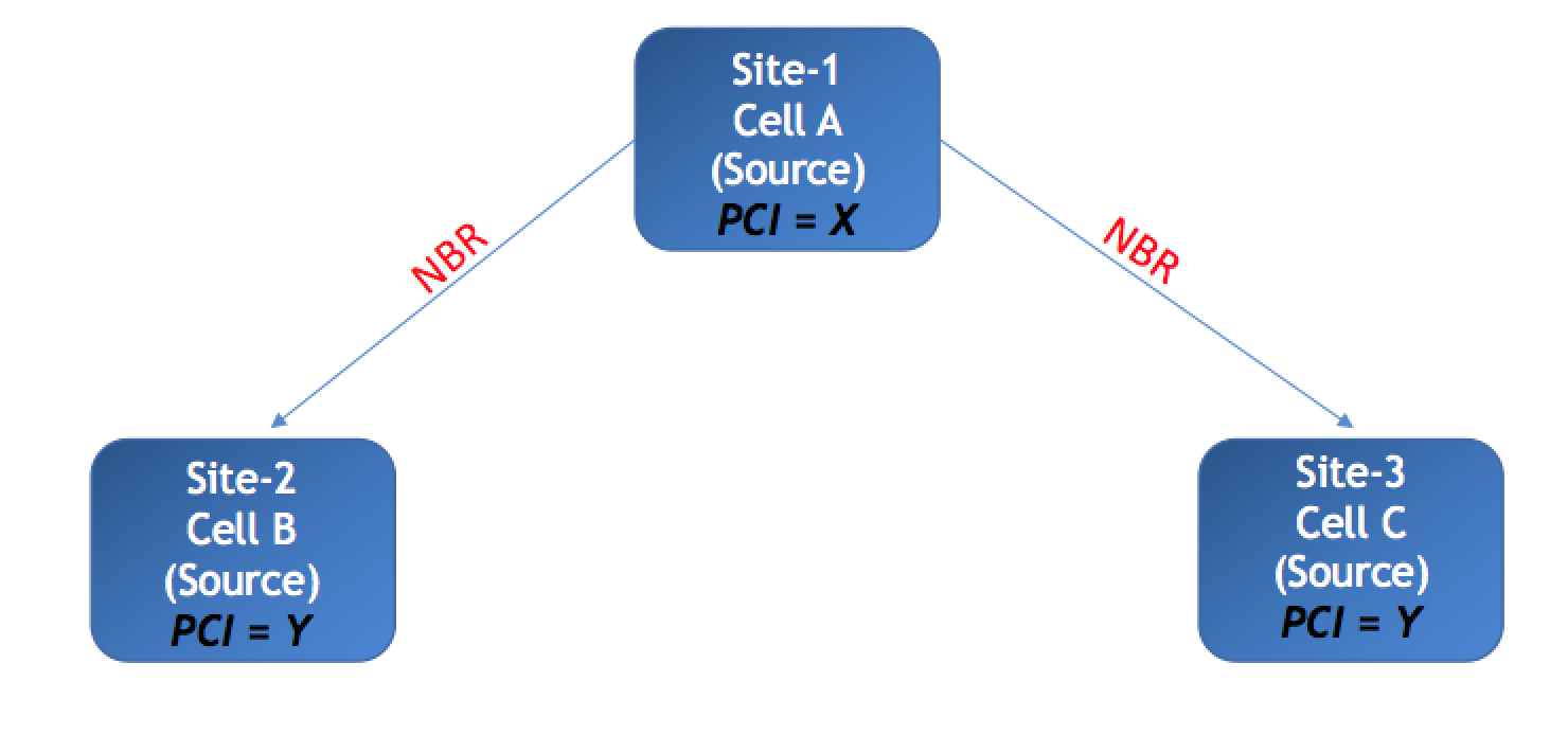
- Ideally, two NBRs of the site should not have same PCI between them. For instance, Cell-A has NBR Cell-B and Cell-C and both of them have the same frequency, then the PCI of Cell-B and Cell-C should not be identical. This is difficult to maintain in a LTE network but this issue can cause PCI confusion and handover failures
Rule#2 PCI mod3 & mod6
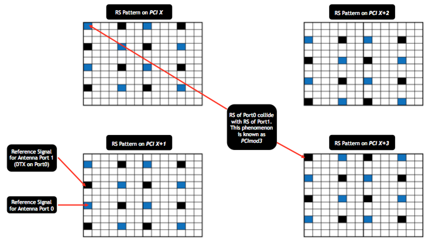
Let’s dig a bit deeper and understand how different vendors do the PCI planning. One approach is to use the same group (same SSS) on one site (3 sector sites) which is the PCI-Modulus3 planning technique. This is much similar to what is depicted in the Figure 9 (above). The PCI is also used to indicate the location of RS along the frequency axis. Consider that the PCI=X will have the RS located at the first sub-carrier then the PCI=X+1 will move the RS downwards by one sub-carrier and PCI=X+2 will move it down by another sub-carrier. The point to note is that there are 2 RS per RB per antenna port in the 1st OFDM symbol. But there are another 2 RS for the second antenna port on the same symbol. These 2 RS are zero-powered (also known as DTX – discontinuous transmission) on the first antenna port. So, when the PCI is changed to X+3, then the RS for antenna port0 moves to the same position as RS for antenna port1 of the PCI=X. This means that for every PCI=X, any other PCI with value of X+3(n) – where “n” is an integer, will have a collision on Reference Signal between the two ports. This is known as the PCI mod3 issue.
However, if the system is only a single port system like most of the IBS systems, then the PCI mod3 will not impact because there will be no reference signals on the second port. Instead, the rule will change to PCI mod6.
An important point to remember is that most of the FDD LTE networks are not time synchronized between sites so the symbols do not usually overlap in time. Therefore, for FDD systems, this rule is not as important as it is for TDD LTE systems which are always time synchronized.
Rule#3 PCI mod30
Just like in downlink, every 3rd or 6th PCI collides on the reference signals, every 30th PCI has the same pattern of uplink reference signals. In uplink, the reference signals are present in the central symbol of the slot and their pattern or base sequence repeats for every 30th PCI. In case, two adjacent cells have same PCI mod30, then the cell can have difficulty in decoding which can result in higher block error rate in uplink. However, this is not a critical issue and very rarely observed in the commercial networks.
Rule#4 PCFICH collisions
In LTE, the PCFICH is one of the channels that gets its location determined based on the PCI. This also means that every PCFICH will repeat its position for some PCIs. Basic rule is that every 50th PCI will have same location of PCFICH for 20MHz channel while every 25th PCI will have same location of PCFICH for 10MHz channels. Such a scenario can cause decoding failures or higher block error rate on PCFICH and since PCFICH is required to decode PDCCH so it can cause DTX (decoding failure of grants on PDCCH).
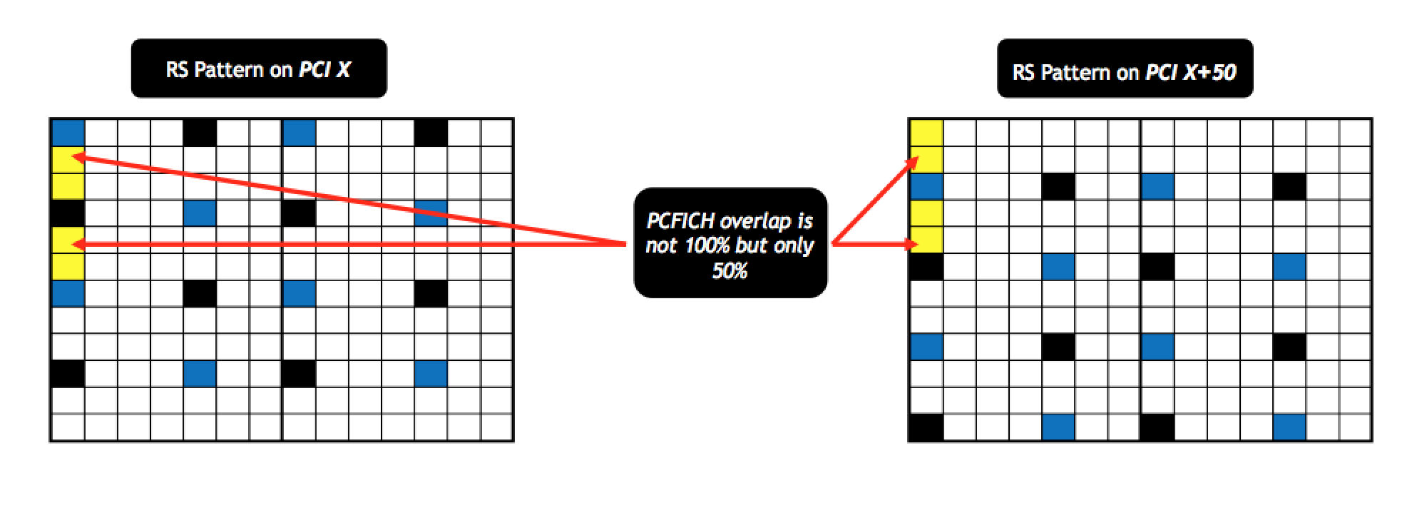
But once again it is difficult to observe in FDD systems and another fact that most of the documents overlook is that PCFICH consists of 4REGs. Each REG has 4 REs but we have reference signals in a LTE system after every 2 REs. So, each PCFICH REG will have Reference Signals embedded inside and that means that 2 PCFICHs usually do not overlap each other completely.
Rule#5 SSS Correlation Issue
There is another known rule that is not really considered as it has no evident impact but I thought it is worth mentioning. As explained, each PCI is made up of PSS and SSS. Each SSS is made up of two length-31 binary m-sequences (m0 and m1) but since SSS are 168 in count so these length-31 sequences are bound to repeat. So, each time m0 or m1 repeat itself, the overall correlation between those 2 SSS values is much higher – in other words such SSS can interfere with each other. As an example, SSS value of 9 can have interference with 10 other SSS values.
However, this type of interference has no effect on KPIs and if the UE fails to decode SSS in first subframe, it can still decode it in the 6th subframe as SSS repeats twice within 10ms. So, such an issue, if observed might delay network entry by 5 to 10 ms which does not have any considerable impact.
